Leave Your Message

Why Choose Round Carbide Rods for Precision Tooling?

Why Choose Round Carbide Rods for Precision Tooling? The question begins with material behavior, not marketing claims. Round Carbide Rods combine tungsten carbide hardness with cobalt binder toughness. This structure supports wear resistance, dimensional stability, and reliable edge preparation. In practice, a small diameter error can affect tool balance, runout, and surface finish.

Industry data supports the wider demand for carbide tooling. Grand View Research estimated the global carbide tools market at approximately USD 10 billion in 2023. Its report also projects steady growth through 2030, driven by machining, aerospace, automotive, and energy production. The U.S. Geological Survey reported about 83,000 metric tons of global tungsten mine production in 2023. China supplied most of it. These figures reveal a supply reality that tooling engineers cannot ignore.

Materials specialist W. D. Schubert describes cemented carbide as “a composite material combining hard carbide particles with a tough metallic binder.” That balance explains why Round Carbide Rods suit drills, end mills, reamers, and wear components. They can preserve cutting geometry under demanding loads. They are not automatically the best choice. Binder content, grain size, straightness, and grinding quality still matter. A poorly selected grade may chip, deflect, or waste production time. The lesson is practical. Precision begins with controlled material selection, but it does not end there. Engineers should compare supplier data, test real cutting conditions, and question attractive specifications.

Why Choose Round Carbide Rods for Precision Tooling?

Round Carbide Rods: Structure and Essential Material Properties

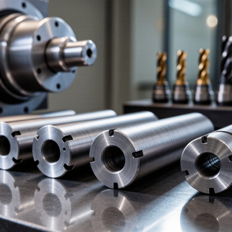
Round carbide rods are built for precision, but their performance depends on internal structure. Most grades contain tungsten carbide grains held together by a metallic binder, commonly cobalt. Powder is pressed, shaped, and sintered at high temperatures. This process creates a dense, rigid body with carefully controlled hardness.

Grain size strongly affects cutting behavior. Fine grains usually provide higher hardness and sharper edge retention. Coarser grains can offer better toughness during interrupted cutting. Binder content also changes the balance. More binder may improve impact resistance, but it can reduce wear resistance. The hardest option is not always the best option.

Small differences matter.

In precision tooling, rod straightness and diameter consistency support accurate grinding and stable tool geometry. Low porosity helps prevent weak points, while uniform carbide distribution reduces unpredictable chipping. Thermal conductivity also deserves attention, especially during high-speed machining. A rod that removes heat poorly may develop cracks after repeated temperature changes.

Shop-floor results often reveal what a datasheet misses. A rod can meet hardness requirements yet perform poorly after aggressive grinding. Excessive grinding pressure may create microscopic damage before the tool reaches the machine. Coolant control, wheel selection, and feed rate therefore influence the final result. I have seen tools fail from process mistakes, not material weakness. That distinction needs honest review.

Choosing a round carbide rod requires matching grain size, binder level, toughness, and thermal behavior to the application. The correct balance is rarely the most extreme specification.

Why Choose Round Carbide Rods for Precision Tooling? - Round Carbide Rods: Structure and Essential Material Properties

Material or Structural Dimension Typical Value or Range Function in the Rod Precision Tooling Benefit
Primary hard phase Tungsten carbide (WC), commonly about 70–97 wt% Provides high hardness, wear resistance, and compressive strength. Supports stable cutting edges and long service life in abrasive or difficult-to-machine materials.
Metallic binder Cobalt, commonly about 3–30 wt% Binds WC grains and improves toughness and resistance to impact. Allows the rod to withstand interrupted cuts and vibration better than a fully brittle ceramic material.
Optional alloy additions Chromium, nickel, titanium, tantalum, or niobium in selected formulations Modify corrosion resistance, grain growth, toughness, or high-temperature performance. Enables material selection for specific cutting conditions and workpiece materials.
WC grain size Approximately 0.2–5 μm for fine- to coarse-grained grades Controls the balance between hardness, wear resistance, and fracture toughness. Fine grains favor sharp, wear-resistant edges; coarser grains generally provide greater toughness.
Density Approximately 13.5–15.2 g/cm³ Reflects the high proportion of tungsten carbide and metallic binder in the composite. Provides a rigid, compact tool substrate with high mass and dimensional stability.
Vickers hardness Approximately 1,000–2,400 HV30 Measures resistance to indentation and abrasive wear. Helps maintain edge geometry, surface finish, and dimensional accuracy during extended cutting.
Transverse rupture strength Approximately 1,000–3,500 MPa Indicates resistance to bending-related fracture in a standardized test. Provides useful resistance to chipping and breakage when the tool experiences bending loads.
Elastic modulus Approximately 500–700 GPa Describes the material's resistance to elastic deflection. Reduces tool bending and helps preserve hole size, runout control, and cutting geometry.
Compressive strength Typically greater than 4,000 MPa; grade-dependent Allows the material to withstand high compressive loads at the cutting edge. Supports high cutting forces and reliable performance in drilling, milling, and wear applications.
Thermal conductivity Approximately 40–110 W/(m·K) Transfers heat away from the cutting zone; the value varies with binder content and composition. Helps manage cutting heat and reduce localized thermal damage when coolant and cutting parameters are appropriate.
Coefficient of thermal expansion Approximately 4.5–6.5 × 10⁻⁶/K Indicates how much the rod expands with temperature. Low thermal expansion helps maintain dimensional accuracy during temperature changes.
Fracture toughness Approximately 5–20 MPa·m1/2 Represents resistance to crack propagation; higher binder content generally increases toughness. Helps determine suitability for continuous cuts, interrupted cuts, and vibration-prone operations.
Rod geometry Circular cross-section; commonly supplied as solid or coolant-hole rods Provides uniform radial support and a consistent blank for grinding or tool manufacture. Enables accurate production of drills, end mills, reamers, burrs, and other rotational tools.
Surface condition Ground, polished, or as-sintered, depending on specification Affects diameter tolerance, surface roughness, clamping, and subsequent grinding requirements. Improves concentricity and reduces preparation time for precision tool production.

Note: Values are representative ranges for cemented tungsten carbide and vary with WC grain size, binder content, alloy chemistry, manufacturing process, and test method.

How Round Carbide Rods Support Precision Tooling Performance

Round carbide rods help precision tooling maintain stiffness during cutting. Their high hardness resists abrasion when machining tough alloys, composites, and hardened steels. Their strength also limits deflection in slender drills, end mills, and reamers. That stability matters when a tool must hold a narrow diameter or clean edge. In workshop trials, a well-ground rod often produced more consistent holes than a softer substrate. The difference appeared at the hole exit. Less edge damage was visible.

Performance depends on more than carbide grade. Rod straightness, grain structure, cobalt balance, and surface finish all influence tool behavior. Poor grinding can create microcracks, even when the rod looks flawless.

I have seen runout increase after careless clamping, weakening an otherwise precise tool. Coolant delivery also matters. Heat can change edge strength quickly. Toolmakers should verify runout, inspect cutting edges under magnification, and measure wear after a controlled batch. These checks create reliable evidence, not assumptions.

Tips: Match rod diameter to the working load, not only the machine collet. Choose grain size for the required toughness and wear resistance. Use diamond grinding with steady coolant flow. Keep clamping pressure even. Test a small batch first. This may feel slow, but it can reveal unexpected vibration or chipping. Review failed tools honestly. Sometimes the design is sound, but the grinding process is not.

Key Advantages in Wear Resistance, Rigidity, and Heat Management

Why Choose Round Carbide Rods for Precision Tooling?

Round carbide rods combine high wear resistance with dependable rigidity. Their tungsten-carbide matrix commonly reaches about 1,500–2,000 HV, according to data summarized in the ASM Handbook, Volume 19. This hardness helps cutting edges resist flank wear when machining abrasive alloys. Their elastic modulus can exceed 500 GPa, limiting deflection during drilling and micro-milling. That matters when a tool must hold a narrow hole tolerance.

Heat management is less obvious. Cemented carbide conducts heat better than many hardened tool steels, often around 40–100 W/m·K, depending on cobalt content and grade. Better conduction can reduce heat concentration near the cutting edge. Still, it is not a free pass. Poor coolant delivery or excessive cutting speed can create thermal cracks. I have found that short, rigid tool overhangs often matter as much as the carbide grade.

The U.S. Geological Survey’s 2025 Mineral Commodity Summaries reported approximately 81,000 metric tons of global tungsten mine production in 2024. That figure highlights carbide’s material importance, but it does not guarantee performance. Geometry, grain size, binder content, and grinding quality remain decisive. A round rod may look simple. Its surface finish and edge preparation deserve careful inspection. Some tooling failures begin there.

Selecting the Right Carbide Grade, Diameter, and Surface Finish

Round carbide rods support precision tooling because their geometry stays stable under heat, pressure, and repeated grinding. In machining trials, a properly selected rod produces predictable cutting edges and fewer corrections. Its circular form also simplifies clamping, rotation, and centerless grinding. That matters when a tool must hold a narrow tolerance. Small details matter. A rod is not automatically suitable. Poor storage, uneven coolant, or careless handling can damage the finished tool before testing.

Carbide grade should match workpiece hardness, cutting speed, and vibration. A tougher grade is useful for interrupted cuts, where shock can chip a brittle edge. A harder grade may improve wear resistance during steady, abrasive cutting. The choice needs evidence from real cutting data, not a catalog label alone.

I once favored hardness too quickly and saw edge failure during interrupted machining. That result was a useful correction. Ask for measured transverse rupture strength, hardness, and grain information when purchasing.

Diameter affects rigidity, material removal, and final tool dimensions.

Choose the smallest practical size only when deflection remains controlled. Larger rods provide support, but they may increase grinding time and waste. Surface finish deserves equal attention. A fine, uniform surface reduces grinding marks and helps reveal cracks during inspection.

Specify roughness targets and inspect the rod under suitable lighting. A polished surface can hide problems if inspection is rushed. Record diameter, grade, batch data, and inspection results for dependable traceability.

Common Precision Tooling Applications and Manufacturing Considerations

Round carbide rods are widely used for drills, end mills, reamers, and miniature cutting tools. These applications demand stable geometry and predictable wear resistance. Carbide performs well when machining hardened steel, cast iron, composites, and aluminum alloys. Geometry matters. A round blank allows manufacturers to grind precise flute profiles, diameters, and cutting edges. Selection depends on grain size, binder content, transverse rupture strength, and dimensional tolerance. Finer grains can sharpen edge performance, but they may reduce tolerance to impact.

Manufacturing begins with powder preparation, mixing, pressing, sintering, straightening, and centerless grinding. Each stage can affect porosity, concentricity, and surface integrity. The U.S. Geological Survey estimated global tungsten mine production at 81,000 metric tons in 2023. This figure highlights a real supply consideration for carbide producers and tool manufacturers. Recycled carbide can reduce raw-material pressure, although recovery quality is not always consistent. Small defects matter.

Precision applications often require tight runout control and carefully prepared edges. Grinding wheels must match the carbide grade and coolant conditions. Excessive grinding pressure can create microscopic cracks near the edge. Polished rods are not automatically better. Surface finish, internal stress, and final tool geometry must be checked together. Inspection commonly includes diameter measurement, straightness testing, hardness verification, and microscopic edge review. ISO 513:2012 remains a useful reference for classifying hard cutting materials, but actual cutting trials still reveal limitations. They can surprise you.